
Designing a backyard deck for my house
Published: 2026-06-16| Words: 3,500 |
| Reading Time: 15 minutes |
This post details my process for designing a backyard deck for my house. Since this post is about showing how to produce the drawings for the deck in order to get a building permit, in this post I'll skip the details of the building process.
See the links to the drawing exchange format (dxf) files at the bottom.
Buying a house without a deck
When we closed on our house almost 10 years ago, it was missing a deck in the back of the house. I was never told the story of why, but from the looks of it, the old deck that used to be there became dilapidated and instead of replacing it, the previous owner demolished it and left a door on the back of the house that had a 4 foot drop!
Needless to say, this was a problem for anyone else buying the house. My loan originator definitely had a problem with this and said that the door must be permanently shut. Since we really liked the house and I was willing to take it "as-is" and have a deck built later, I asked "What do you mean by permanent?" The answer was, "The door must not be able to be opened without special tools." So, after a bit of brainstorming, with the written permission of the owner, I hired a handyman and had him screw three large wooden screws through the door into the frame, thereby closing it shut so that it cannot be normally opened. This (and a few other fixes, like GFCI outlets) was enough to pass inspection and close on the house and everyone was happy.
Since the house was not in "move-in ready" shape, it took us another 2 months of work before we could move in. The back deck however was a bigger project than we had money or capability do at that time, so our back door remained shut for the next year. Finally, I couldn't wait anymore and searched for a contractor to work on the deck. After a few tries, I didn't find anyone that was giving us a quote we can work with and I decided to take matters into my own hands.
I could design and build my own deck, how hard could it be?
High school skills
In my high school it was required for first year students to take drafting as one of the first year classes. I didn't even know what drafting was, but soon I learned that it meant to make technical drawings on semi-transparent large-format vellum paper. This was paper and pencil drafting, on a drafting desk, all the work was done by hand. If you made a mistake, you erased the lines with an eraser and tried again. If it was too messy, you started all over. You used a mechanical pencil with lead of different softness, with which you had to make lines of different thicknesses and patterns, and you had to use triangles and compasses to make angled lines and circles. We never got far enough to make crazy complicated curves by hand but it would have been fun.
The manual drafting classes spanned the entire first year. Throughout the class students were given various drawings to complete, of increasing difficulty. Looking back, the drawings were not very difficult, but for beginning students with zero drafting skills, it could be a bit of work. However, I really liked it, even though I didn't take it seriously at the time. I didn't always get good grades on my drawings, since I made mistakes, but I did well enough to get a good grade in the class. However, if you're in the engineering mindset, and also in the DIY mindset, this kind of experience is invaluable. I am forever grateful that our high school had this experience. I'm sad to say that our class of the year 2000 was one of the last ones to do drafting by hand, as it was removed from the curriculum during my time in high school.
In my second year of high school we also had shops. I thought it was really cool that my school offered these as classes and I really liked all of them. I took auto shop (learning about internal combustion engines and general car maintenance), wood shop (working with chisels, saws, and drills to make things out of wood), electric shop (making simple electric circuits, such as one where it sounded an alarm when a string was pulled), and finally Computed Aided Drafting (CAD), which was the computer equivalent of the hand drafting class we had the first year.
Overall, I really appreciated how our technical high school balanced the hands on classes with the more academic classes. If I were to do it again, I would do it the same way, and maybe take the classes more seriously so I get more out of them.
All of this to say that I was confident that I could draw up the plans for our deck.
The Plans
So I started to do just that. I spent 3 months working on a deck design on paper. Part of that time was spent re-learning my CAD skills on a new software (I chose LibreCAD because it reminded me of AutoCAD Lite, but there are many options), part of it was measuring out various parts of my house and deciding how big we want parts of the deck to be, and part of it was making sure that I followed our building codes for our village.
A lot of the work was because I had to produce 9 different drawings to show various details.
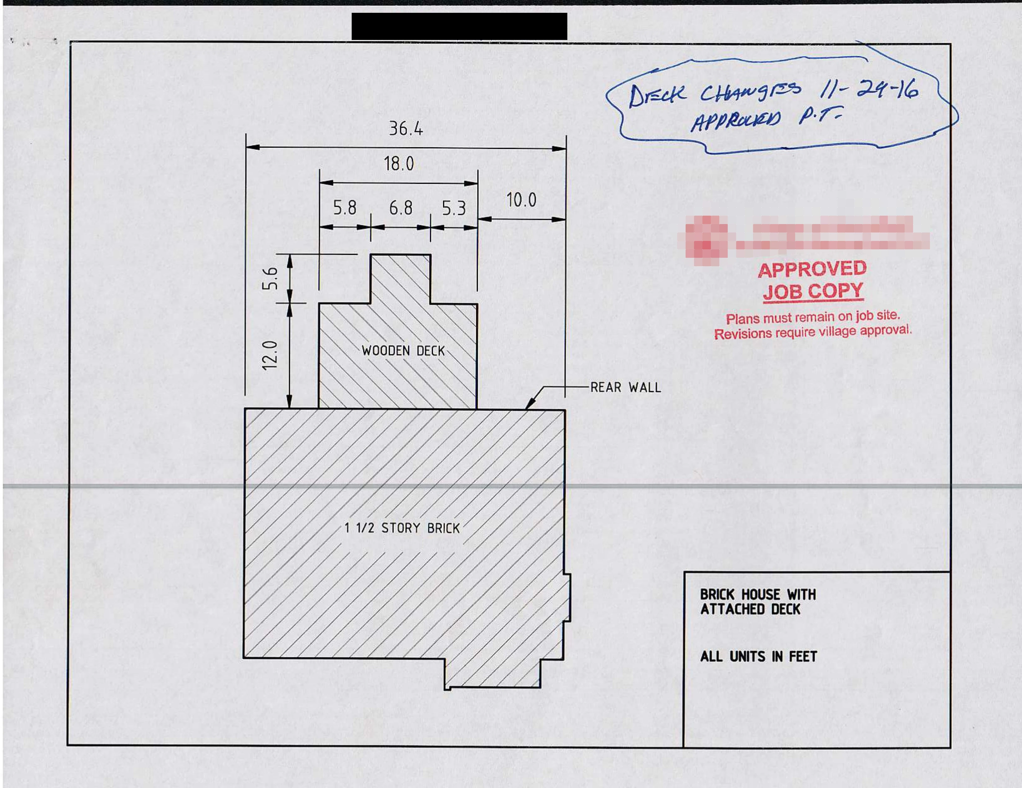
House and Deck View
The first view needs to show where the deck will be in relation to the house and the relative dimensions (a top view).

The deck in relation to the house (full size image, dxf file).
By making the drawing, I figured out that we'd be increasing our house's first floor square footage (28 feet by 36 feet = 1008 square feet) by 216 square feet when adding the deck. That's about 20% more usable space that we didn't have before!
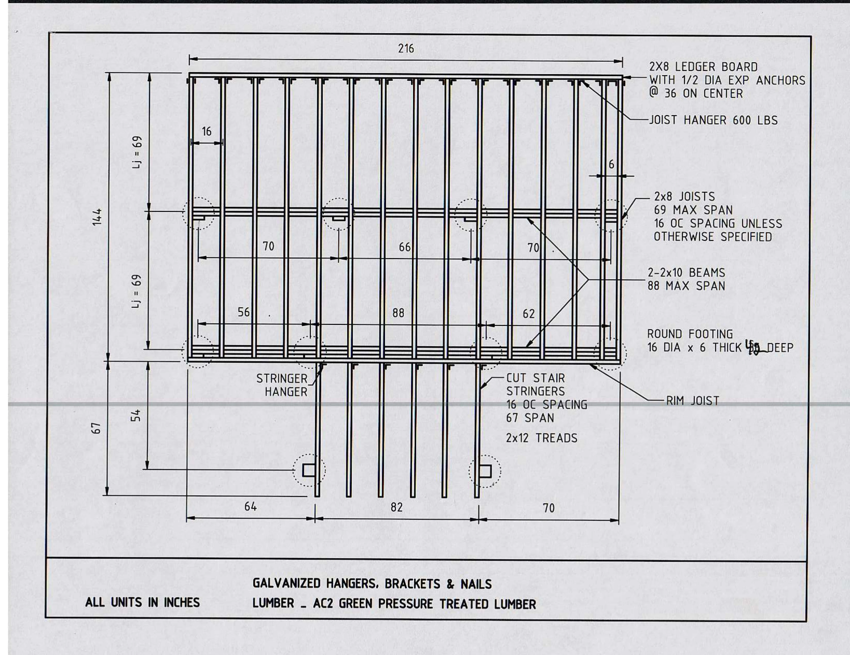
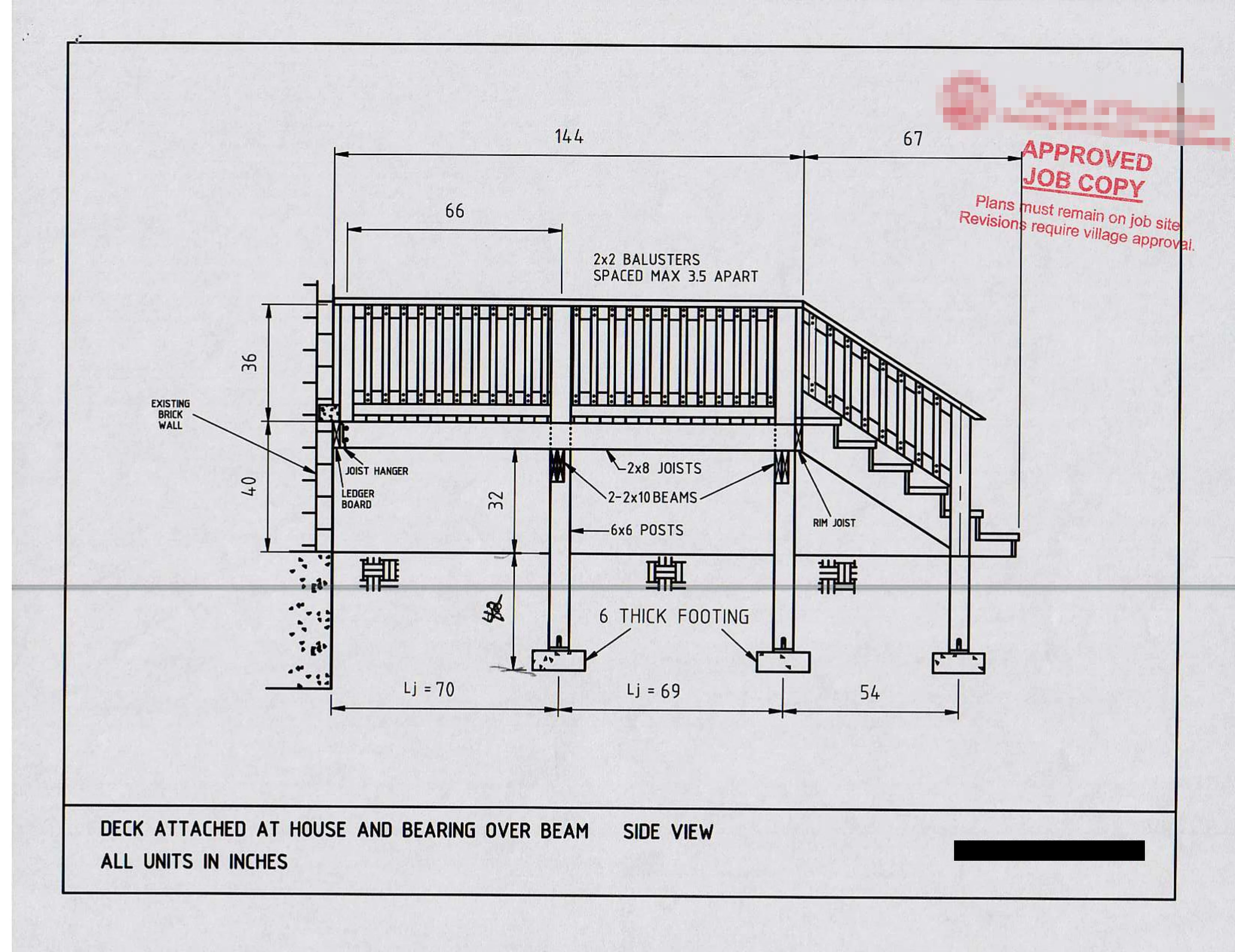
Framing View
The framing is the main support of the deck. This view shows a few critical parts, including the ledger board that connects the deck to the house, the rim joist that supports and caps off the end of the joists, and the stringers that connect to the rim joist and support the stairway of the deck down to the ground.
The drawing also shows where the circular concrete footings will be underneath the framing, which is useful for knowing where to dig.

Details of the framing of the deck. See full size and dxf file.
It's not very clear from the drawing, but it shows 4 by 4s supporting this framing on top of the concrete footings. This is wrong, I ended up using 6 by 6s instead, for better support and easier connections to the beams using carriage bolts.
Also, the drawing says the footings are 16 inches in diameter. This ended up being overkill and I made footings of 12 inches diameter instead, because I could easily rent and operate an auger with a 12 inch drill.
Footings Views
Another two views need to show where the concrete footings will go and how deep (both are side views).
Note that the inspector made some annotations on the sheet where I didn't have a length for the depth. The village wanted the footings to go down to 42 inches in the ground, to avoid movement due to the earth freezing and thawing with the seasons.

The inner set of supports for the deck with the footings. See full size and dxf file.

The outer set of supports for the deck with the footings. See full size and dxf file.
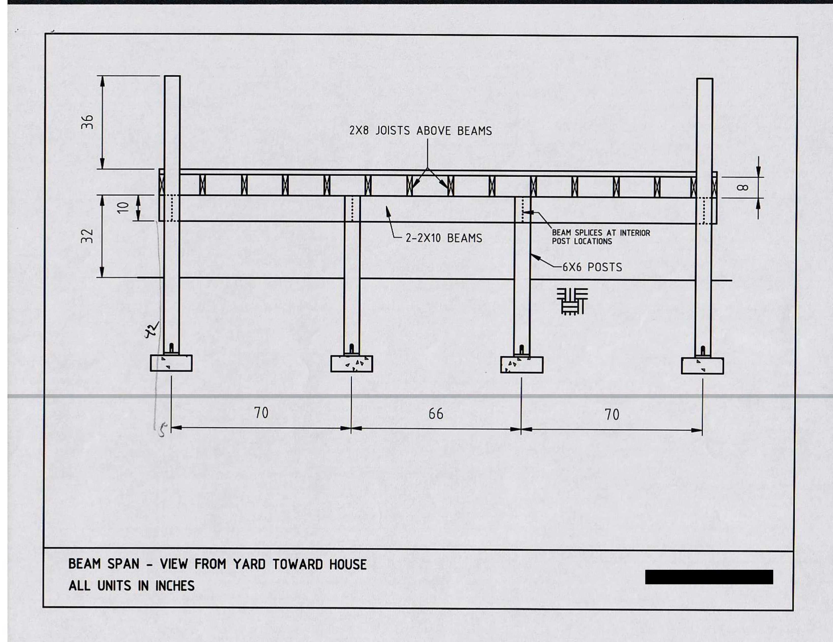
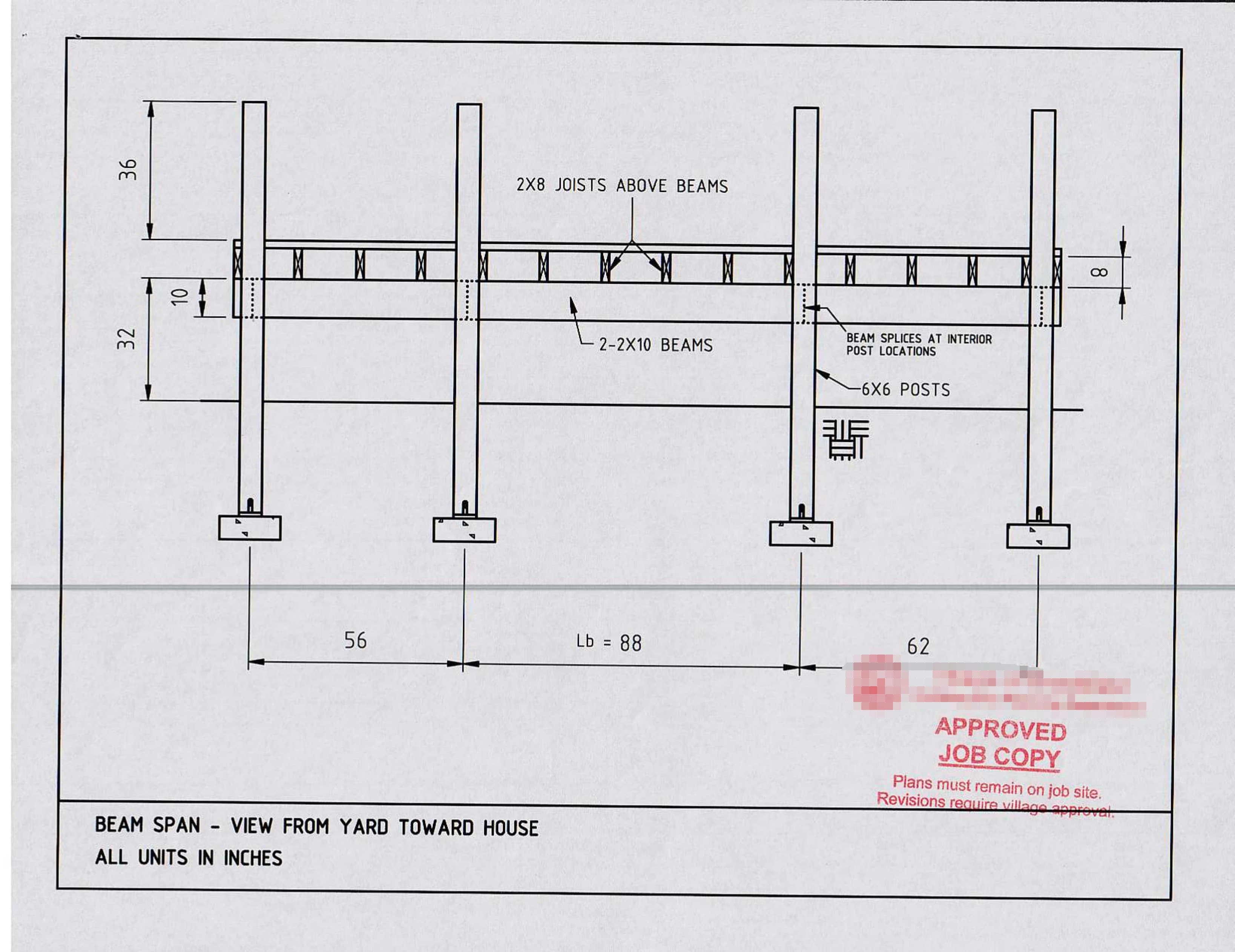
After the footings, then the deck framing drawings have to show how the underside support posts, beams, and joists will be. This is an important part of the deck because it forms the platform on which the top visible part of the deck will be built.
Note that in the drawing I have the beams split into pieces, however, I was able to get 20 foot long 2 by 10 beams so I didn't have to cut them. They're one continuous piece across the deck, making it stronger and more secure.
Also the concrete footings are drawn completely wrong. In reality the concrete goes from the bottom of the hole up to a few inches above ground level. You really don't want wood touching soil or ground water.
Railing with Balusters View
Then a view for the railing, and balusters showing how the finished deck will look from the side.

A side view of the railing with balusters. See full size and dxf file.
Deck View
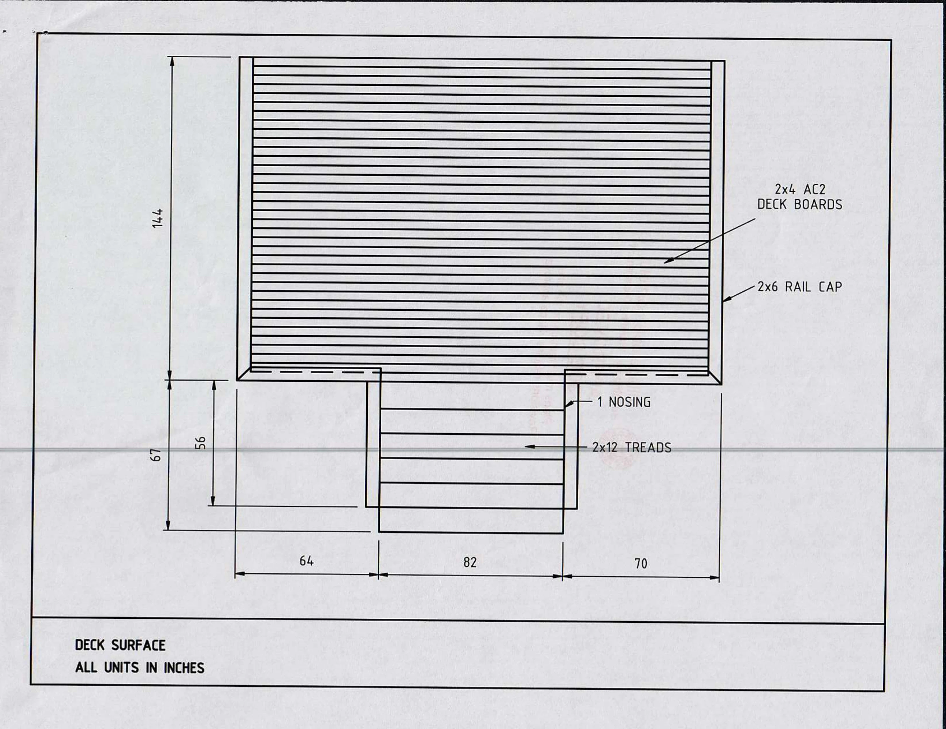
The inspector also wanted a view of the deck surface, showing the detail of how the deck wood would be laid out.

A top view of the deck surface. See full size and dxf file.
Notice that the deck is not symmetrical between the left and right sides of the stairway (one side is 64 inches while the other is 70 inches). This is because we wanted a clear view of the yard from the dining room window when looking out. So we aligned the stairs with the window and widened them to give a better view of the yard. This turned out really nice, we have a nice view of the yard as we walk through our dining room.
Other Drawings
Finally, a few more drawings showing the dimensions and assembly details of some of the critical pieces.
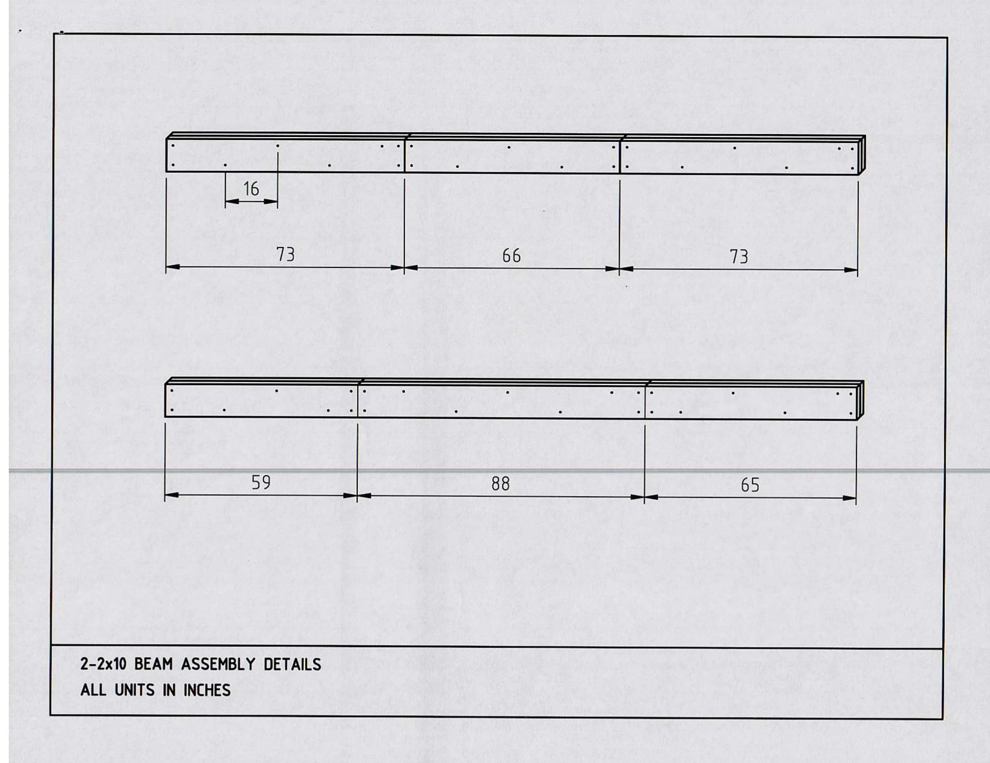
The beam assembly details
This drawing shows the spacing of the screws that will hold together the main load bearing beams of the deck. The screws have to be offset to more evenly spread out the load each screw will be under. By offsetting the screws, you avoid breaking them.
However, the drawing was not completely accurate, because I didn't need to cut the beams into pieces, instead each beam was a sandwich of two very long 2 by 10 pieces of wood without cuts.

Each beam ended up being one complete, uncut piece because I was able to get a 2 by 10 that was 20 feet long! See full size and dxf file
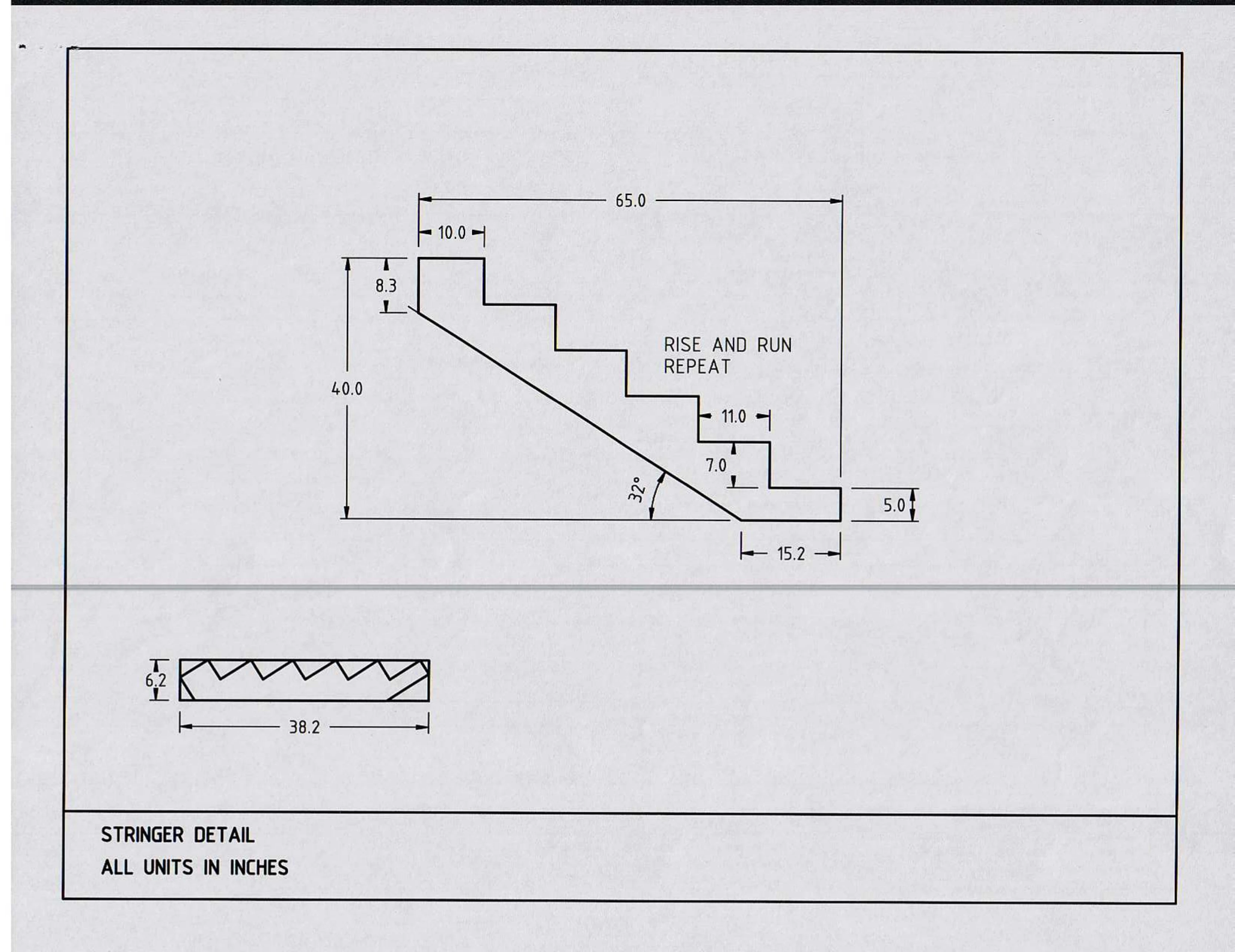
The Stair Stringers
The stringers support the steps going from the deck down to the yard. Stringers are sold pre-made at the store, so I didn't have to make them myself, but I didn't know this at the time. Also, I thought it would be a fun challenge to make 6 identical (more or less) stringers.
The angles and dimensions of the stringers are all custom, but it turned out very nice, with the stairs having a spacious and lazy (not too steep) feel to them, since the rise (7 inches) is much less than the run (11 inches).
I ended up using a more stringers than in the drawing since I wanted more support for the stairs.

The detail of one stringer. See full size and dxf file.
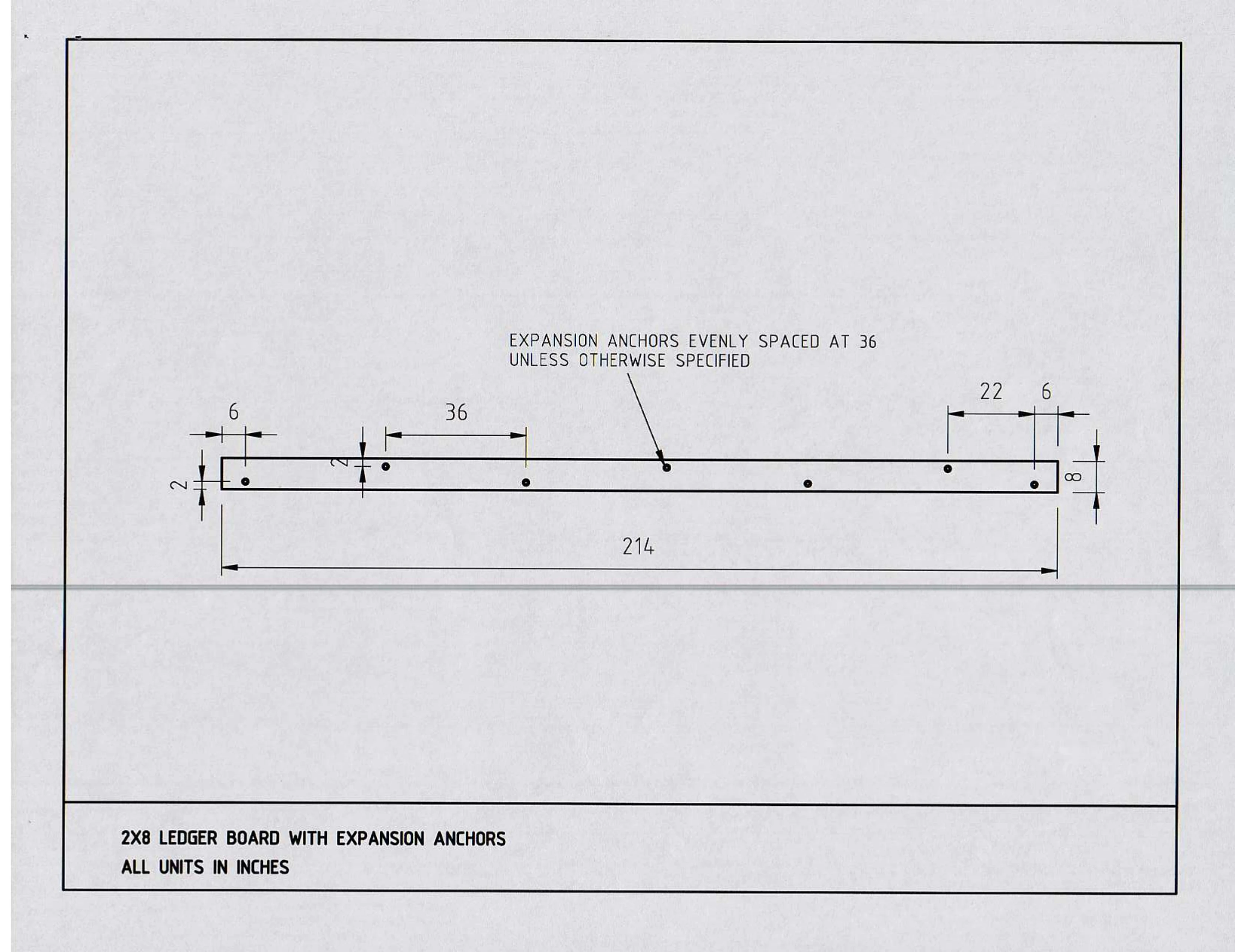
The Ledger Board
The ledger board attaches the deck to the back wall of the house. This is a wood to brick connection that must use expansion anchors. It's not shown in the drawing, but I ended up putting flashing over the top of the ledger board to avoid water seeping in between the ledger and the brick from the top. This ensures that the wood of the ledger board will avoid rot and last a long time.

Details of where the expansion anchors will go on the ledger board. See full size and dxf file.
Thoughts on the planning process
Overall, it was a lot of manual work to produce all the drawings because the 9 drawings were independent of each other. When I had to change something in the plans (like a distance between something and something else), I had to manually update every drawing that showed that thing. Then I had to double-check and triple-check that the drawings still made sense together. If I had to do it again, I'd probably find a way to do a 3D model and produce 2D drawings from it. However, I didn't have the patience to learn 3D parametric modeling (or I didn't find a program that I wanted to learn), so I was happy to use my existing skills to get the job done, even if it took longer.
The local building inspector was helpful during the process and gave me a small pamphlet of about 8 pages that described the various requirements in more approachable language. While the pamphlet was still technical, it wasn't dry and impenetrable like building codes could me. He was also the one that reviewed the various versions of the plans before approving the building permit. I was grateful for his input, and we went back and forth about 5 times, but I was really happy once I had an approved job copy of the plans. The job copy had to be available for the inspector at all times during their inspection. Once I got the permit, work could begin.
Building the Deck
After the plans were approved, I started with digging the holes for the concrete footings. Overall it was 10 holes, that had to be at least 42 inches deep and at least 12 inches in diameter. At first I hired someone to make the holes, but by the time they barely finished a third hole using a manual hole digger, they said they threw out their back and never came back to finish the job. It was up to me again to finish the rest of the holes.
I started with the manual hole digger too. It was slow and painful, and it chewed through your palms even with gloves on, but I persisted. After some time, I got to the point where the hole was even too deep for a manual hole digger. I searched and found that you could rent a gas-powered auger (a drill for making large holes in the ground). Since I needed 12 inches in diameter, I needed at least a two-person auger.
So I rented a two-person auger and conscripted my brother-in-law Bruno to help. Well, we got the job done, but it wasn't any easier. That two-person auger is a monster to handle, and when it starts lifting the dirt out of the ground, it's like you're lifting weights at the gym, while the weights are trying to knock you to the side. We finished the rest of the holes and decided we're never doing that again.
After the holes were dug, we had the inspector come out to inspect the holes before they're filled. I think the main thing he was looking for was to make sure I had dug them deep enough (and yes, I did, even deeper than was required), and that I had left some space at the bottom for extra concrete to form a sort of a bulge.
After that, I started to fill the holes, which meant I had to buy about 80 to 100 bags of concrete or so, and rent a concrete mixer that I ran for about two days before I made enough concrete to fill 10 holes. I used these cardboard concrete cylinders and I taped a trash bag at the bottom, that way the concrete would form a bulge at the bottom of the footing and would be almost impossible to move by the freezing and thawing cycles of the earth. Then I put the cardboard cylinder in the holes and filled them up with the concrete I was mixing.
One flaw in hindsight is that I left too much concrete at the top, so it wasn't flush with the ground, but about 3 to 5 inches above. This was not necessary, even if you wanted to protect against wood root, because water wouldn't pool at the top anyway. So I would have made the top of the footing closer to the ground so it looks nicer.
Anyway, after that, I put together a large $5,000 order of treated wood from a lumber yard, with 6 by 6s, 4 by 4s, and all kinds of other cuts of wood for the rest of the parts of the deck and had it delivered to the house. A week later they came by and dropped off the massive order, after which I put some in the yard and the rest in the garage.
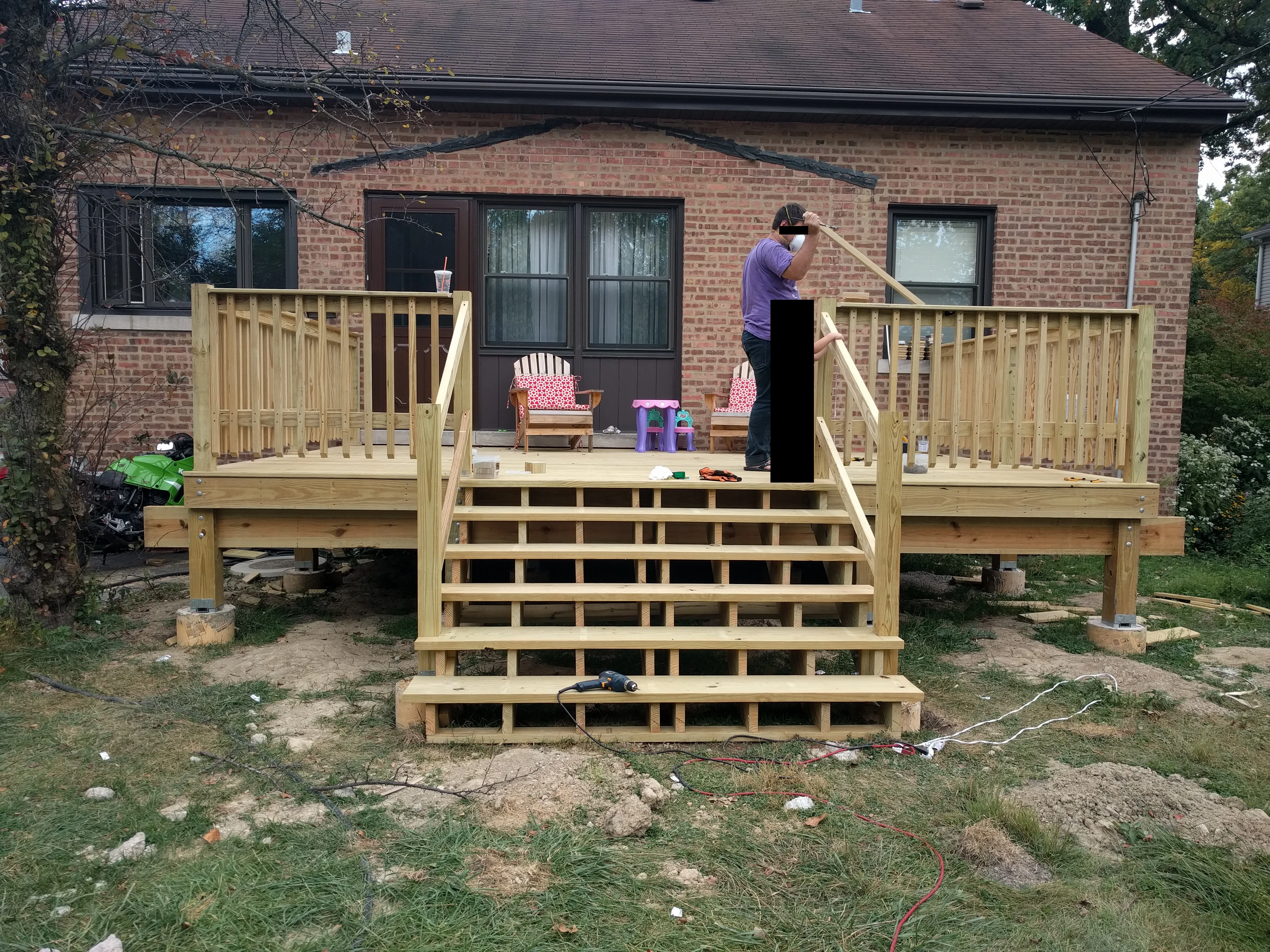
It took me another week and a half to build out the frame of the deck, and then have a framing inspection. And another two weeks before I had a finished deck and the final inspection.

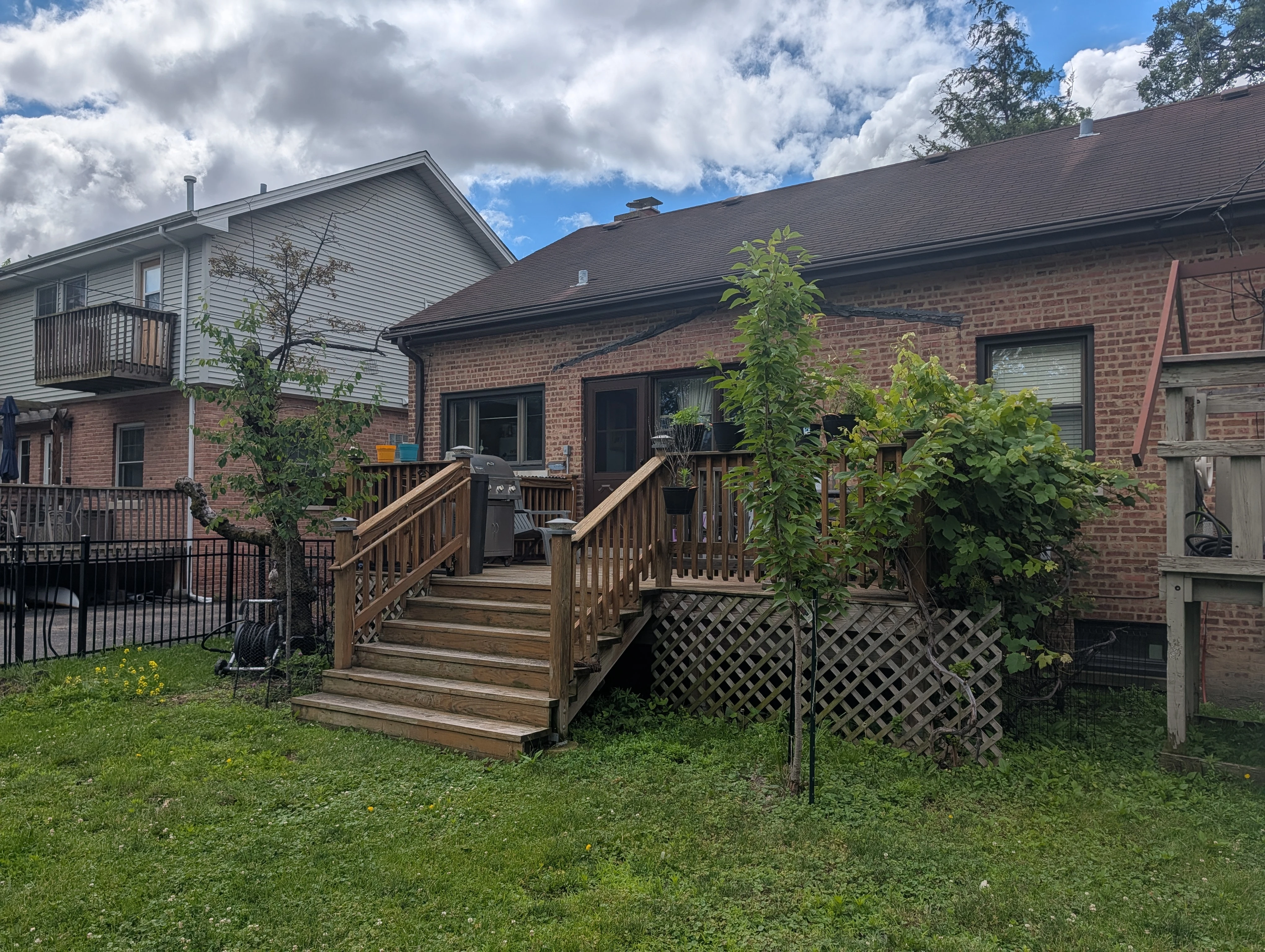
The nearly finished deck. See full size image for more detail.
I worked with power hand tools like a drill and various hand saws, and a table saw. Those were enough to do all the cuts and make all the wood joints and put everything together.
I also learned a lot about the different ways to connect wood to each other using various metal pieces, instead of just nailing them together.
The Hindsight
There were a few parts where my plans were just wrong. For example, in my plans I showed a 4 by 4 wood post going deep into the ground. That's wrong, you never want wood touching wet soil. Instead, all of the ground part was concrete. And once you have a full concrete footing, then you want to use a 6 by 6 post instead of a 4 by 4. I also should have designed the deck to have more of an overhang, so I can hide the footings under the deck and have a nice clean finished look.
As I mentioned, I thought I would run a 4 by 4 from the bottom to the top and that would support the railings. That was wrong too, because the frame is independent of the railing, and you attach the 4 by 4 to the frame, it doesn't need to go all the way down to the soil. Instead you use sturdier 6 by 6s for the frame.
But these are things that you learn as you go, or if you're in the business, you learn from someone more experienced. I was able to adjust as I went along and still do a good job.
I also made the deck 18 feet long, which was much bigger that the one that was there before (you can see the tar of the previous roof on the back wall of the house), which was a problem because it went to the middle of our bedroom window (see the right side in the picture). We really like the size of the deck, so I don't think I would have made the deck smaller, but maybe I could have come up with a better way to incorporate the window so it doesn't have a railing right outside.
Another flaw is how close one of the concrete footing is to the catch basin (sewer on the left side). I should have been more mindful to move the footing further away from the catch basin. I'm also lucky that none of the footings were above the sewer line that goes from the catch basin around the house (to the right, so it runs right under the deck) and out to the front, or I would have drilled a hole in the sewer line!
Another hindsight is that I ended up spending about $6,000 for the deck everything said. If I had put another $6,000, I could have had a professional do it, and it might have been worth it, considering how much time it took me. The hardest part is finding someone that you trust to do a good job at a decent price, and in my case I just didn't find that contractor and thought I could save money doing it myself. I did save some money, but at the cost of a lot of personal time and added labor.
9 years later
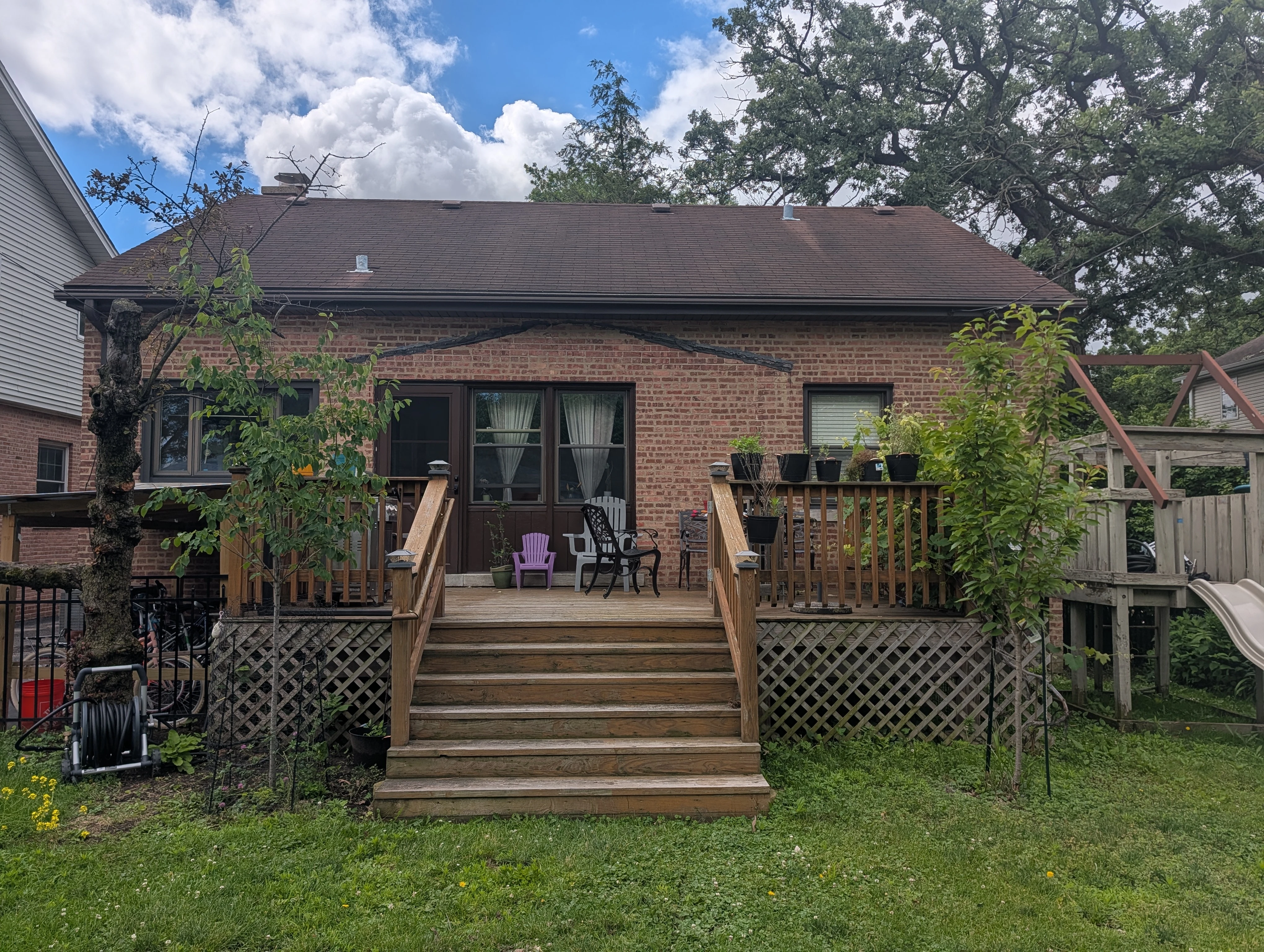
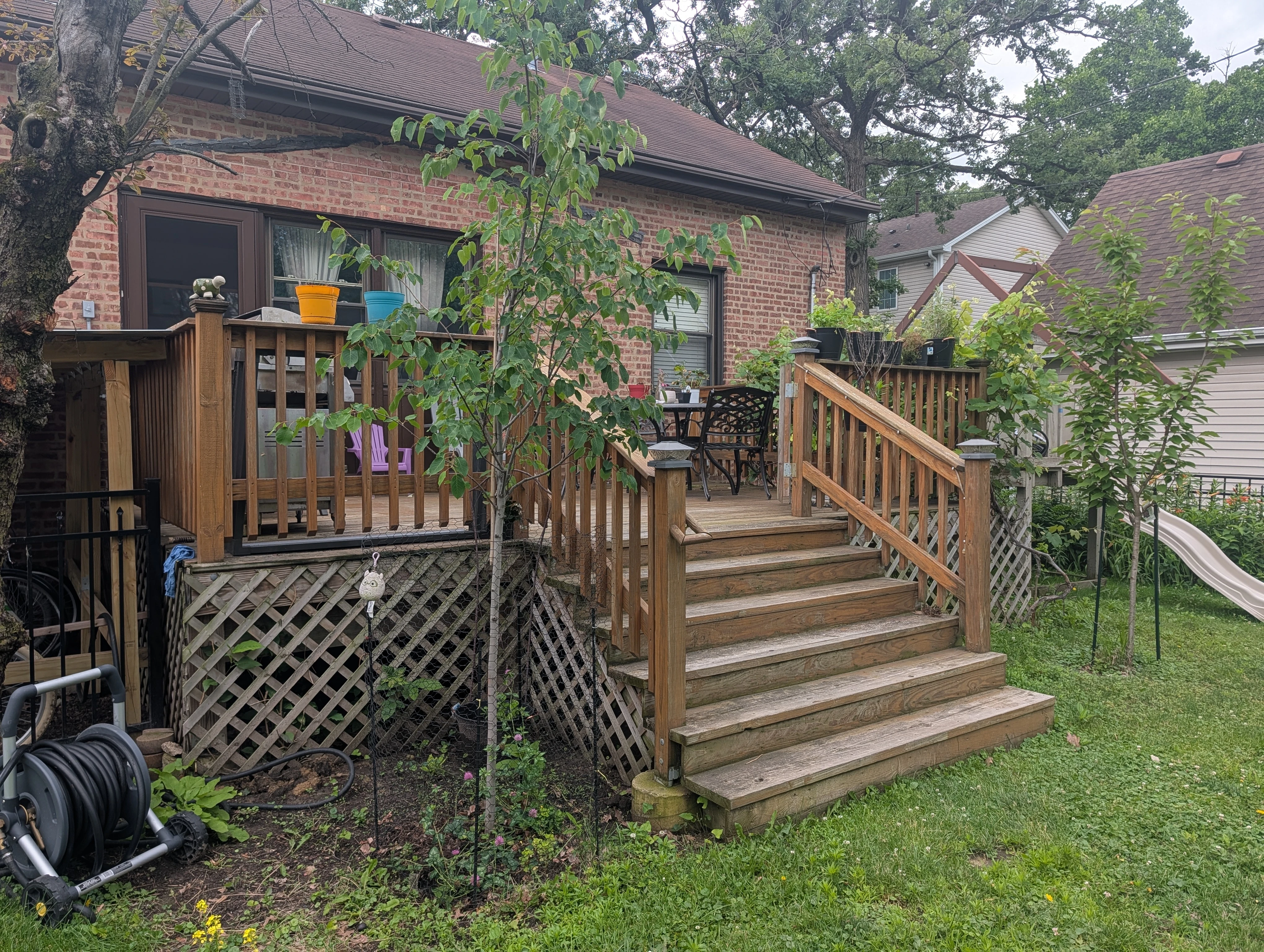
Since I'm writing this post 9 years after I finished the work, here's how the deck has held up:


The current deck after 9 years of use (views from the front, left, and right). The gray color on the wood means it's now time for the stairs and the deck wood to be cleaned and resealed. See full images for more detail: front, left, right.
After we finished building the deck, we cleaned and sealed the wood (deck, stairs, and railings) with a deck wood sealer that had a 4 year warranty. Depending how much water contact the deck has, the sealer can last from 3 to 6 years. For my deck, it's now time to clean and reseal the deck wood again to renew and continue protecting the wood (this is also partly why I also had the idea to blog about the deck project).
Periodic maintenance is one of the downsides of using natural wood. When pricing the wood order, I asked about composite (engineered) wood instead of lumber. The cost was 2 to 3 times more, and I also had a few more concerns, so I didn't go for it.
Conclusion
Overall I was very happy with the deck and that I was able to finish the project. The work is solid, it's lasted us 9 years and if I maintain it properly will probably last another 10 years with no problems. And I have the confidence that if I need to change or redo any part of the deck, I know exactly what to do.
The time I took to make the plans, even though it was necessary for getting a permit, I would still do it even if I didn't need a permit. Having a finished plan helped my building phase to go super smoothly. I knew exactly where things needed to go, how big to make them, and how to put them together, and I knew ahead of time that we had put in the thought to have things turn out how we want them.
Overall I'm proud of my work and I hope it inspires others to see a similar project from start to finish.
Links
This blog post was discussed on Hacker News. Thank you for all the thoughtful comments.
Drawing files on this page:
